Building a drone from scratch
DIY drone
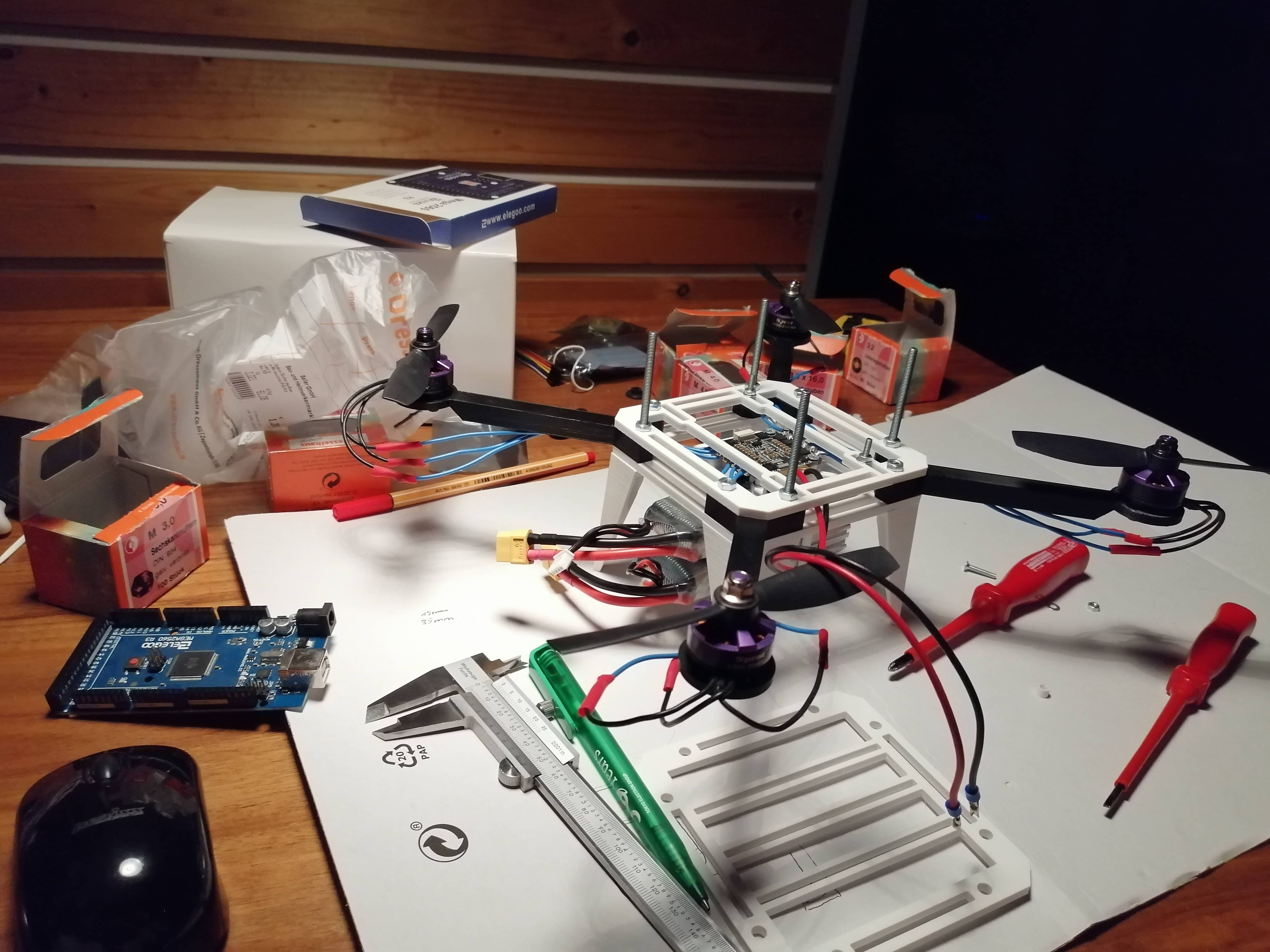
My aim in this project was to construct a drone capable of auto levelling itself and flying. This means that it needs to detect its orientation relative to the ground and boost the right motors to remain stable in the air. I had to learn a lot about electronic parts as well as control theory.
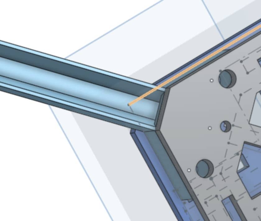
Every part of the frame was custom-designed for a specific purpose in a CAD-Software and printed with a 3D-printer. This way every component like sensors or chips could be mounted together tightly.
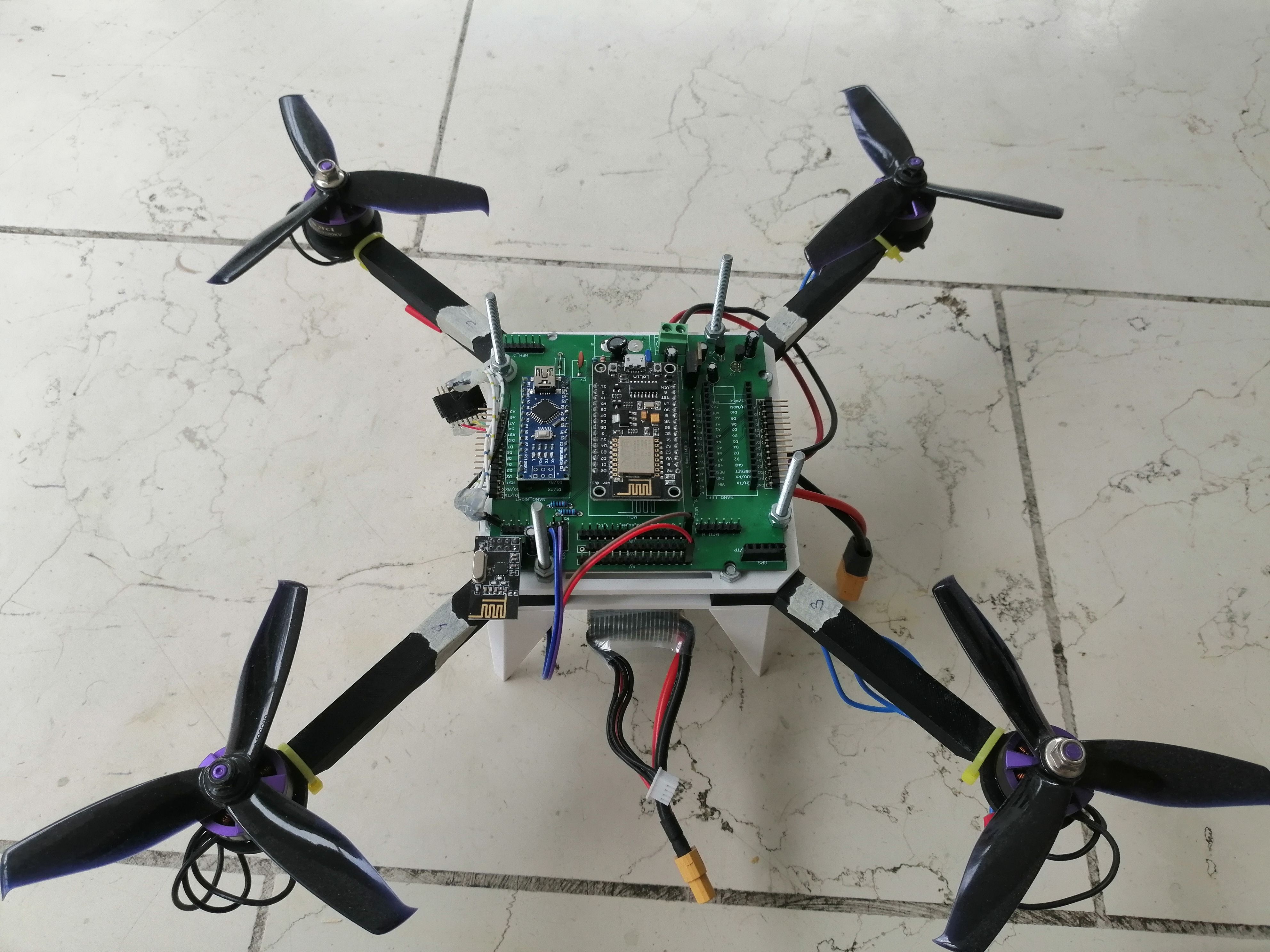
The picture to the right presents a top-down view of the drone, which clearly shows the two microcontrollers that can easily be replaced (explain mechanism more closely, is it click in?) and the remaining space for a third one. This multicore solution provides the drone with more performance and parallel processing. It required a custom PCB board in order to solder the electronic parts together tightly.
Software
The aforementioned microcontrollers each have their own specific tasks.
The one in the middle is an ESP8266 (120MHz). It processes sensor data, runs the control code, and transfers results to the slower processor via I2C.
The second processor is the ATmega328 (16MHz). Its role is to send thrust data to the ESCs.
Main core
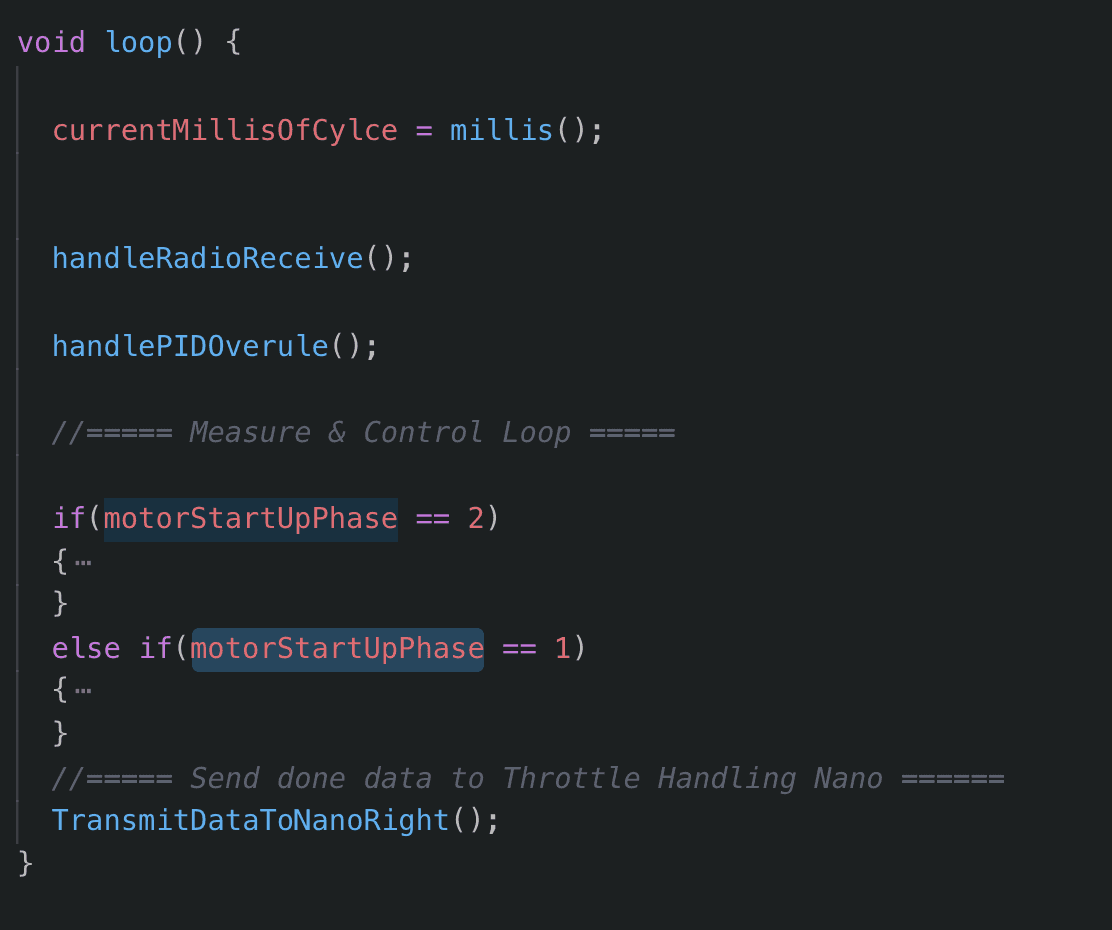
The main core has four tasks: receives remote control data via a 2.4GHz module, checks motor status, evaluates IMU data, and runs PID logic to determine throttle. It transfers values via I2C to the next core.
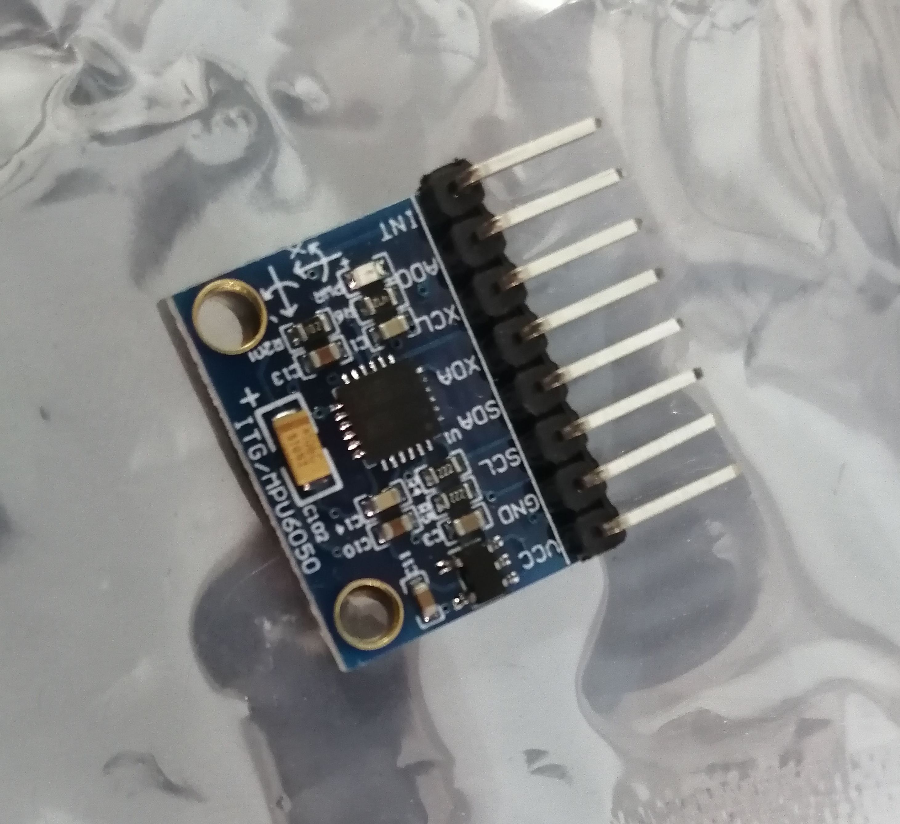
IMU
An IMU (inertial measurement unit) detects orientation using linear acceleration and angular velocity. The MPU-6050 provides this data and communicates via I2C.
Read more in my (German) paper: "Aufbau und Funktion eines Drohnensensors".
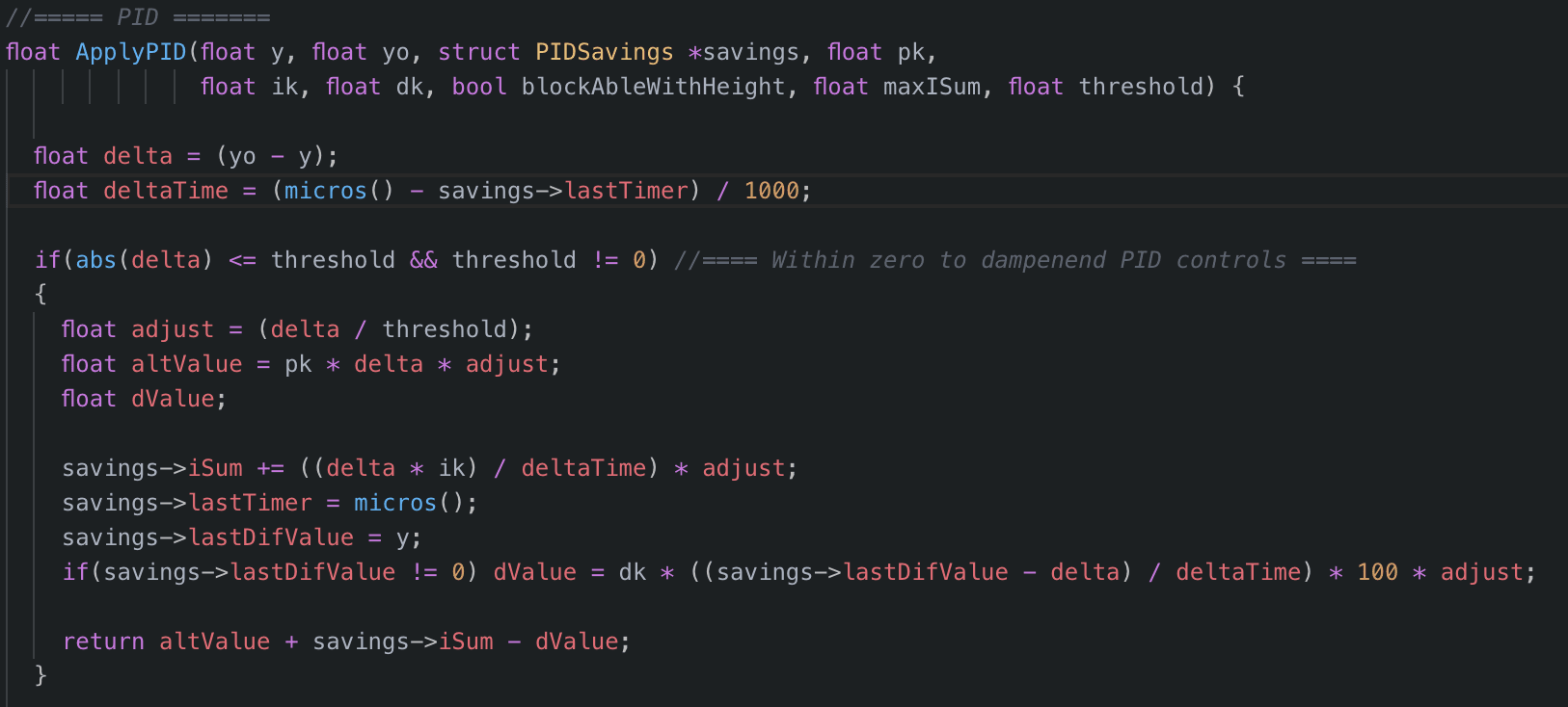
PID
A PID controller regulates thrust with three parts:
- P (Proportional)
- I (Integral)
- D (Derivative)
Each part has a tunable constant (pk, ik, dk).
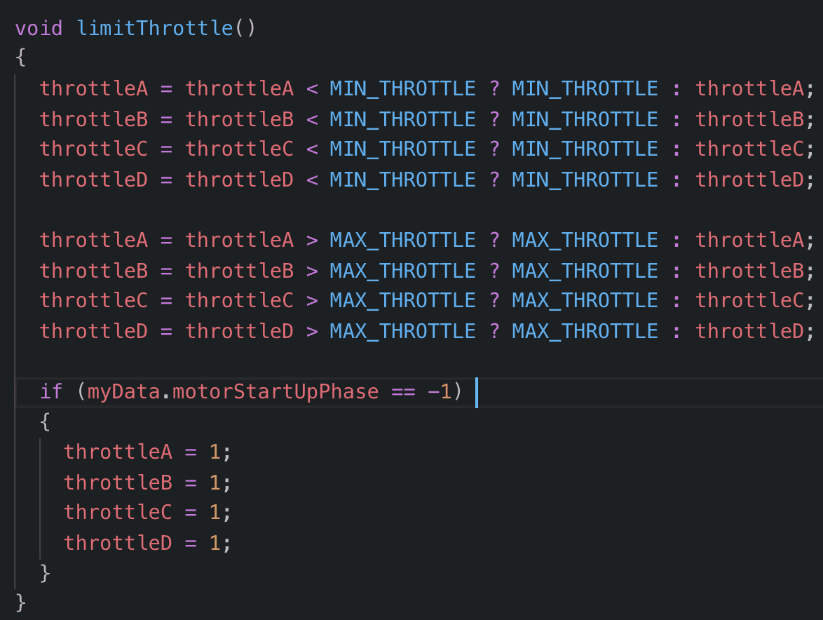
Secondary core
The slower core converts thrust values to analog signals via OneShot125. To meet protocol timing, assembler code is used. It also contains security logic like min/max thrust caps and an emergency stop.
Construction
Every part of the drone has a custom mount to optimize space, balance, and weight. The 3D-printed frame includes holes to reduce weight.
Printing
This video shows the process of printing a frame. Battery slots are visible on both sides.
The landing legs are printed tall to make space for the battery.
Electronic
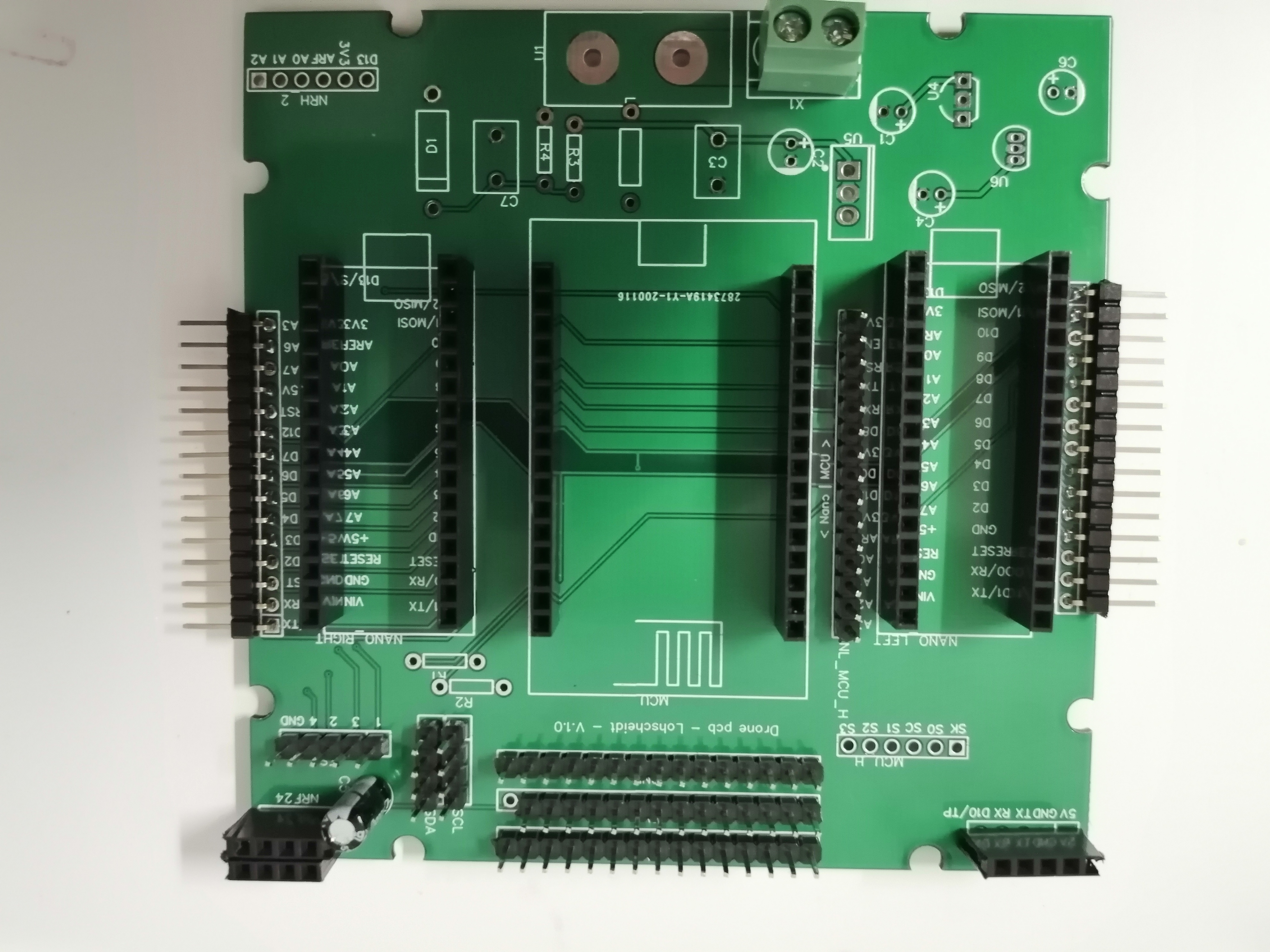
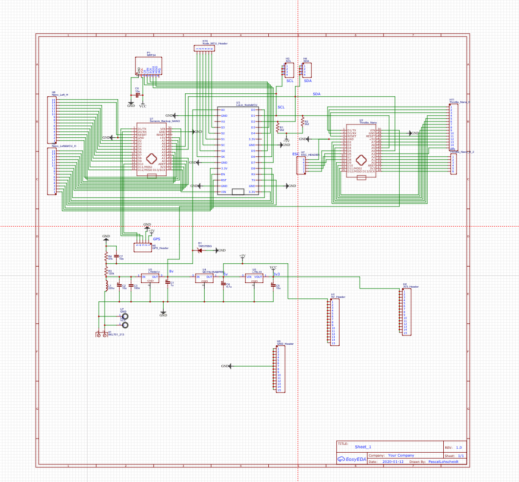
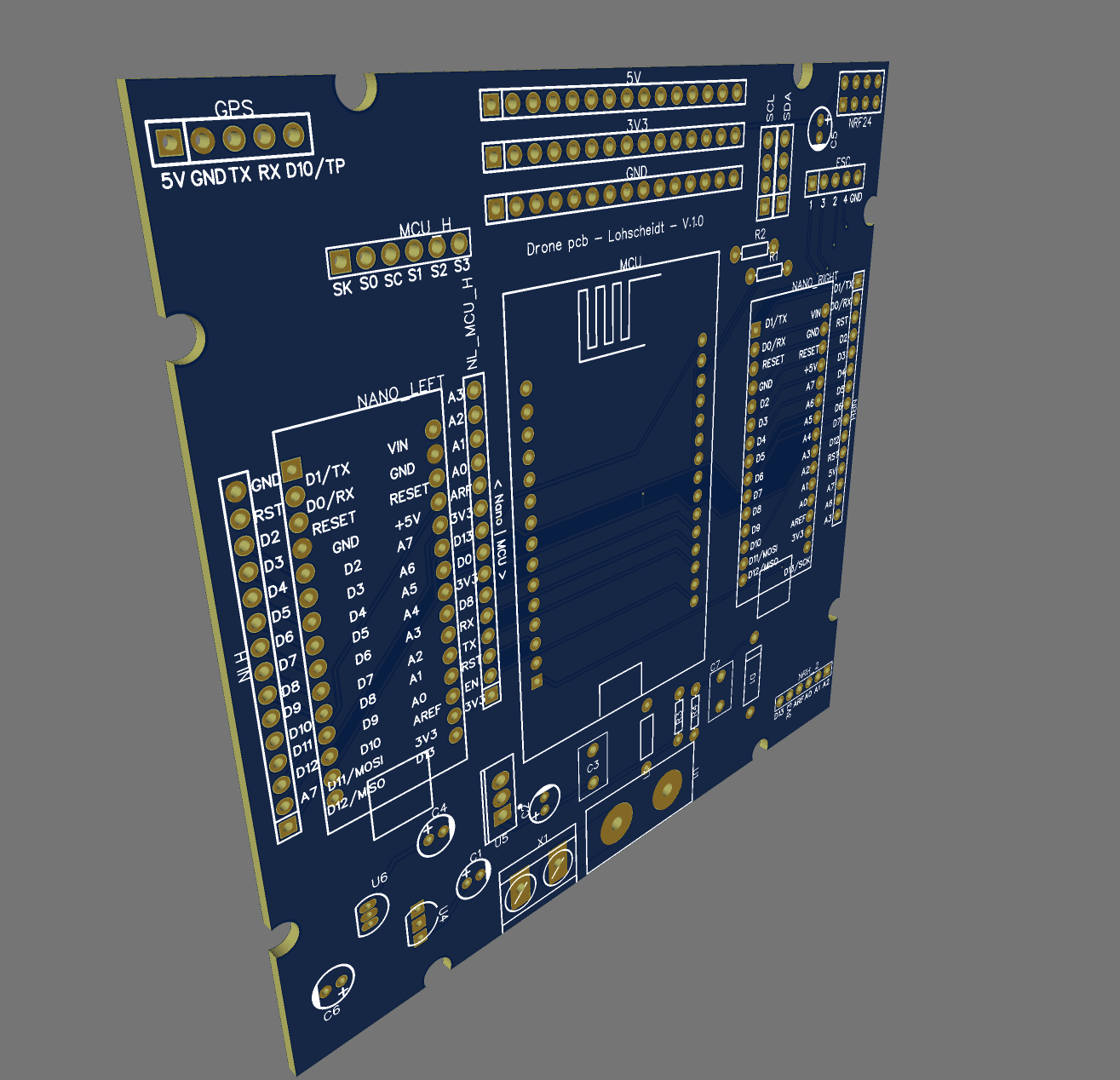
PCB - Circuit board
The drone has a DIY PCB made in EasyEDA. It includes voltage regulators for 9V, 5V, and 3.3V and has pluggable microcontroller shields for easy replacement.
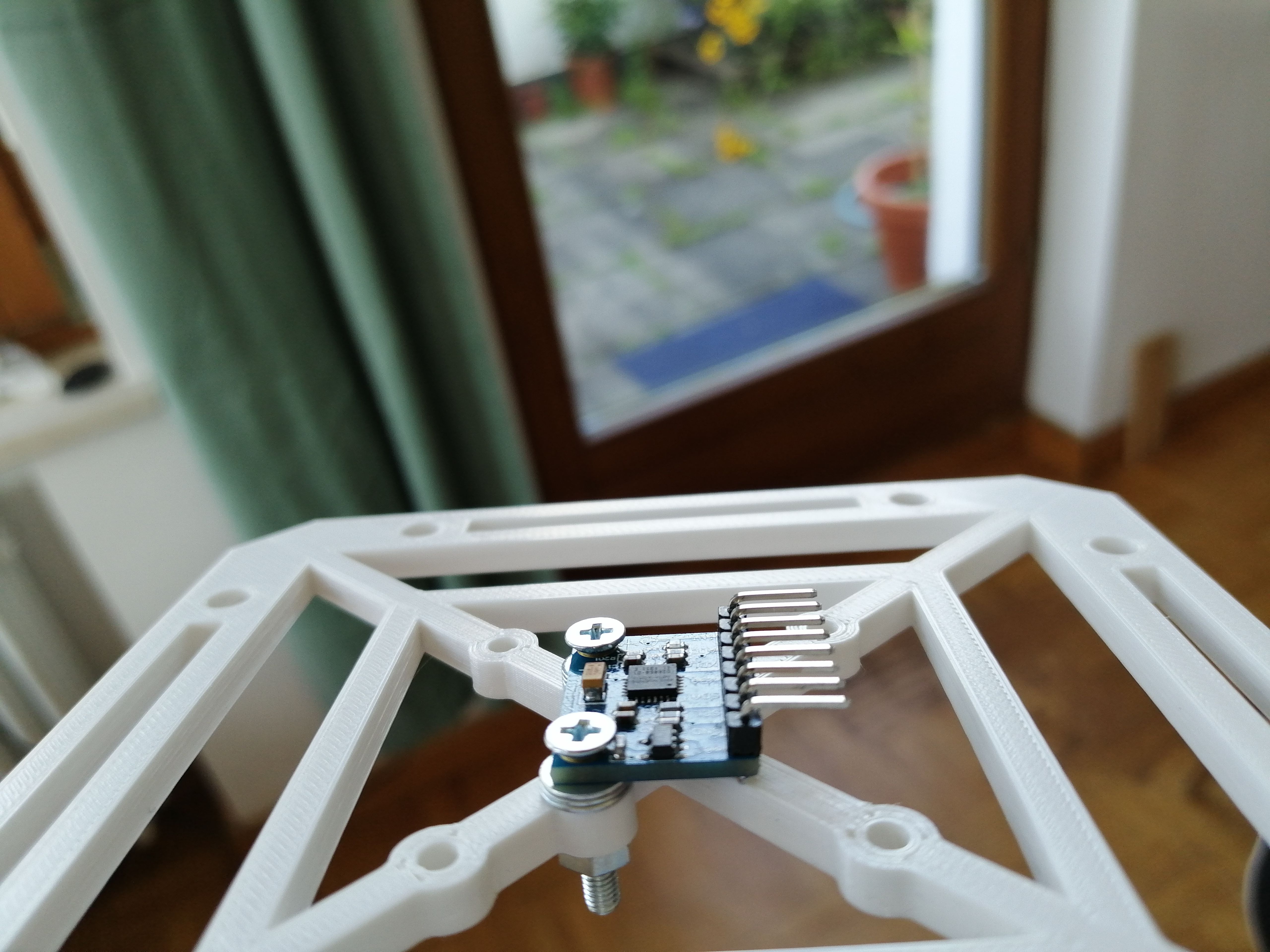
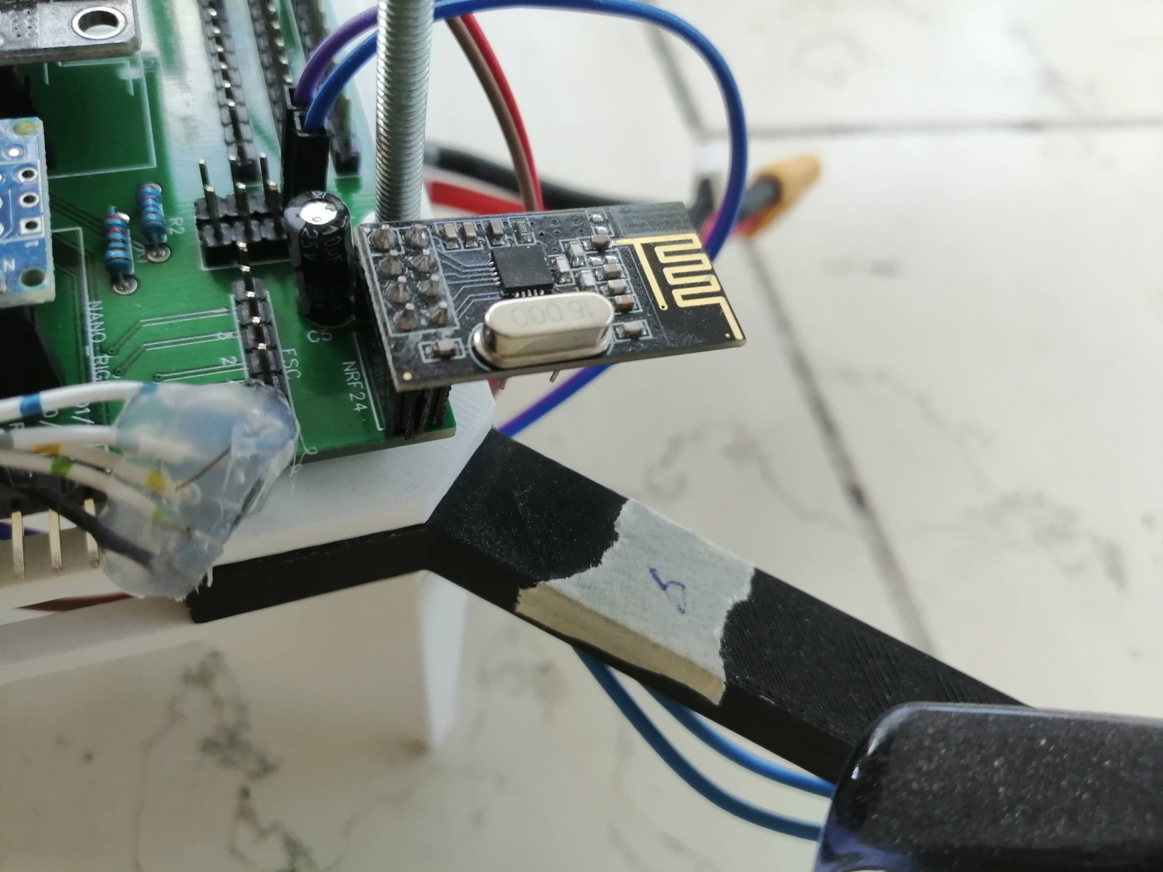
NRF24
The NRF24 module provides 2.4GHz communication with multi-channel support. A capacitor is recommended to prevent voltage drops.
Tuning
Tuning the PID values is critical. This test cage allows the drone to rotate on two axes. The video shows improvements in stability as values are adjusted remotely.
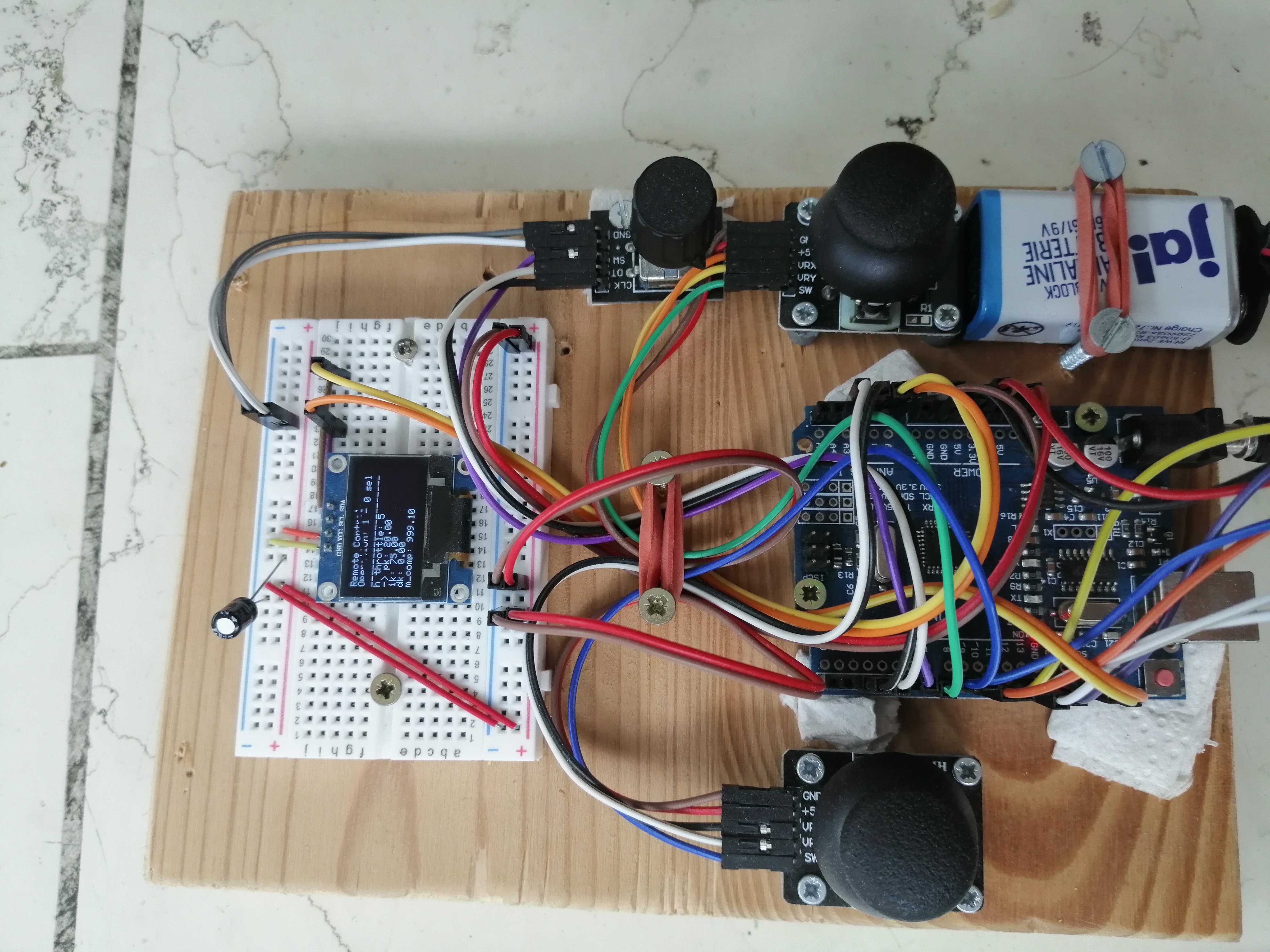
Remote control
The remote uses the same 2.4GHz module, with two joysticks and a rotary encoder. It also has a display for showing PID values and actions like “start engine” or “emergency stop”.